
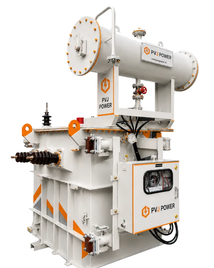
Why correct Transformer sizing matters
Selecting Transformer capacity is not simply a matter of adding every connected load. An undersized Transformer may run hot, suffer excessive voltage drop, trip during motor starting and age prematurely. A severely oversized Transformer can increase capital cost and operate for long periods at an inefficient loading level.
The right rating should support the Plant maximum demand, starting and cyclic loads, power quality conditions, ambient temperature, planned expansion and the required level of operational redundancy.
Step 1: Prepare a complete load schedule
Begin with a load list covering all major Plant equipment. Record the rated kW or kVA, supply voltage, power factor, starting method, operating pattern and whether each load is continuous, intermittent or standby. Separate process-critical loads from utilities and non-essential loads.
Production machinery, process heaters, furnaces and welding equipment.
Induction motors, pumps, compressors, fans, conveyors and cranes.
HVAC, lighting, office, utility and fire-fighting loads.
UPS systems, battery chargers, Variable Frequency Drives and rectifier loads.
Future machines, planned production lines and expansion allowances.
Step 2: Calculate maximum demand, not only connected load
Connected load is the sum of all installed equipment ratings, but most Plants do not operate every load at full output at the same time. Apply realistic demand and diversity factors based on the production sequence, operating shifts and historical data from similar facilities.
The basic three-phase sizing relationship is: required kVA = maximum demand in kW divided by operating power factor. For example, a 900 kW maximum demand at 0.90 power factor requires approximately 1,000 kVA before allowing for starting duty, harmonics, ambient conditions or future growth.
Use measured maximum-demand data when expanding an operating Plant.
For a new Plant, validate diversity assumptions with the electrical consultant and process team.
Do not apply one blanket demand factor to every load category without reviewing how the Plant operates.
Check whether contractual demand and utility-sanctioned load impose additional limits.
Step 3: Check motor starting and voltage dip
Large motors can draw several times their rated current during starting. Even when the steady-state load is within the Transformer rating, simultaneous or direct-on-line starting may cause an unacceptable voltage dip, nuisance tripping or process interruption.
Review the largest motor, the starting method and the number of motors that may start together. Star-delta starters, soft starters and Variable Frequency Drives can reduce starting demand, but the complete electrical system still needs a voltage-drop and protection-coordination study.
Step 4: Account for harmonics and special duty
Modern Industrial Plants often contain Variable Frequency Drives, UPS systems, data equipment, rectifiers, arc furnaces and welding loads. These non-linear loads create harmonic currents that increase winding and stray losses and may require a specially designed Transformer or derating.
Duty can also be affected by frequent load cycling, high ambient temperature, altitude, restricted ventilation, solar inverter operation and highly unbalanced loads. These conditions should be stated in the technical specification before the Transformer is designed.
Share the expected harmonic spectrum or Total Harmonic Distortion values with the manufacturer.
Specify ambient temperature, altitude, enclosure and indoor or outdoor installation conditions.
Identify fluctuating, cyclic, rectifier, furnace, solar or other special loads.
Confirm neutral loading and phase-unbalance conditions for extensive single-phase loads.
Step 5: Add a justified margin for expansion
A practical design normally includes spare capacity, but the allowance should reflect an actual expansion plan rather than an arbitrary percentage. Too little margin can force an early replacement, while excessive spare capacity can leave the Transformer lightly loaded for years.
As an illustration, a calculated demand of 1,000 kVA with a justified 15 percent expansion allowance becomes 1,150 kVA. Subject to motor-starting, harmonics and site checks, a standard 1,250 kVA Transformer may be considered. The final selection must be confirmed through a detailed load-flow and system study.
Step 6: Decide between one Transformer and multiple units
One larger Transformer may offer a simpler installation and lower initial equipment count. Two or more Transformers can provide maintenance flexibility, phased expansion and partial redundancy, especially where production downtime is costly.
When Transformers will operate in parallel, their voltage ratio, vector group, impedance, tap position, polarity and other electrical characteristics must be compatible. The switchgear fault rating and protection scheme must also suit the resulting short-circuit level.
Assess the financial impact of a complete Plant shutdown.
Separate critical and non-critical loads where continuity is essential.
Consider N+1 capacity for processes that cannot tolerate a single point of failure.
Allow safe isolation, maintenance access and future interconnection in the Panel design.
Information to include in the Transformer enquiry
A complete enquiry helps the manufacturer select and design the Transformer accurately. Along with the required kVA rating, provide the system voltage, frequency, vector group, impedance, tap range, cooling method, winding material preference, loss limits, installation environment and applicable IS or IEC standard.
Maximum demand study and detailed load list.
Motor ratings, starting methods and simultaneous-starting sequence.
Harmonic-producing loads and power-quality data.
Utility fault level and upstream protection details.
Expansion plan, redundancy philosophy and expected loading profile.
Required Testing, documentation, accessories and after-sales support.
Final Transformer selection checklist
Before releasing the purchase order, confirm the approved General Arrangement drawing, Guaranteed Technical Particulars, guaranteed losses, temperature rise, impedance, insulation level, accessories, routine Tests, Type Test references and warranty scope.
Transformer sizing should be reviewed by a qualified electrical engineer using the project single-line diagram, load-flow results, short-circuit study and protection-coordination study. A nameplate kVA calculation is the starting point, not the entire engineering decision.
PVJ Power note
PVJ Power supports Industrial Plants, EPC contractors and consultants with project-specific Transformer selection, design review, Manufacturing, Testing documentation and after-sales service. Share your load schedule and technical specification for a detailed Transformer proposal.
Discuss your requirement